
// D.T.MUX NANOX
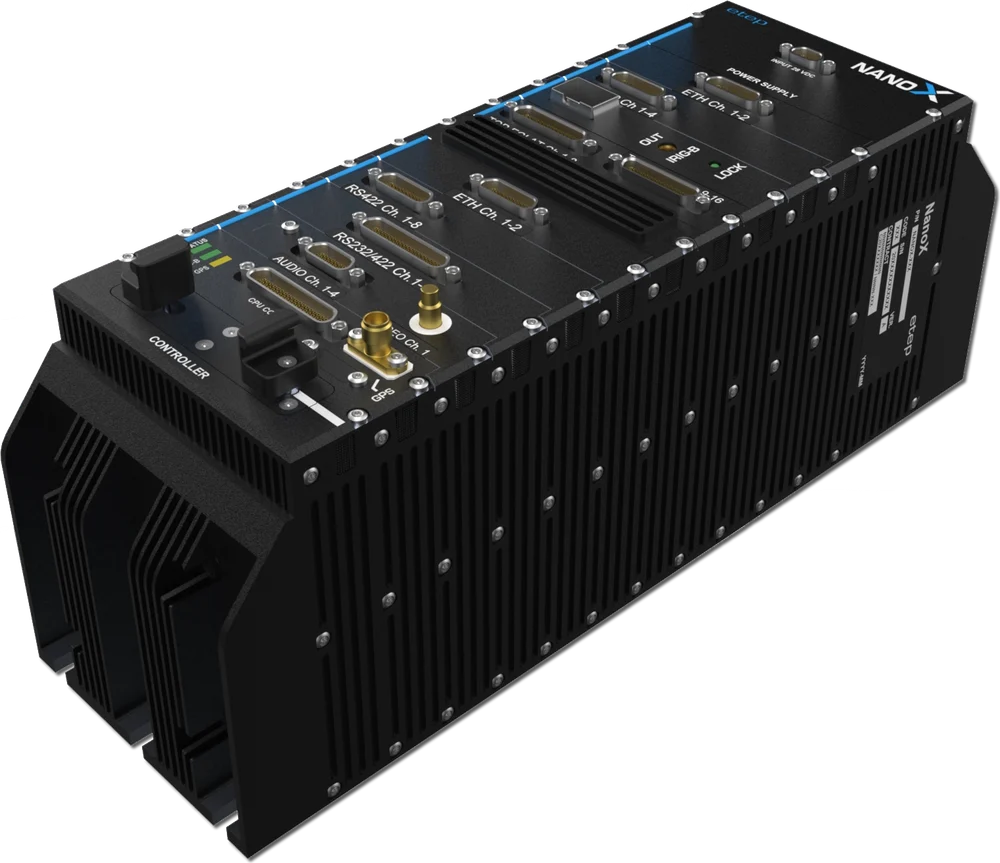
NanoX acquisition modules
Up to sixteen stackable modules per NanoX, chosen family by family: analog sensors, avionics buses, serial links and video, each with its variants and its part numbers. Pick the ones your test needs, then build the unit in the configurator.
- Module families
- 26
- Analog / sensors
- 13
- Digital / buses & video
- 13
- Slots per NanoX
- 16
ANALOG / SENSORS
Analog and sensor modules
Conditioning and conversion in the module: voltages, temperatures, strains, vibrations, pressures, positions and pulses.
- VOLTA
Advanced analog (all-in-one)
The Swiss Army knife of analog: voltages, thermocouples, RTDs, strain gauges and ICP accelerometers — all on one module.
View the module - VOLT RP
Analog voltage
The most universal input: measures the analog voltage of any sensor, differential or single-ended, with software-programmable ranges.
View the module - ICP RP
ICP / IEPE accelerometers
Listens to your structure: directly powers and conditions ICP/IEPE piezo accelerometers for vibration analysis.
View the module - THERMO
Thermocouples
Takes temperatures wherever it gets hot — engines, brakes, avionics bays — with type K, J, T, E, N support and cold-junction compensation.
View the module - THERMI
Thermistors (PT100)
Precision temperatures with PT50 / PT100 / PT1000 probes — when tenths of a degree matter.
View the module - PRESS RP
Pressure
Reads pressure sensors across the aircraft: hydraulics, fuel, pitot lines, cabin.
View the module - GAUGE RP
Strain gauges
Measures how the structure works: strain gauges bonded to wings, frames or shafts, in full-bridge (FB) or quarter-bridge (QB) completion.
View the module - BRIDGE RP
Bridge signals (piezoresistive)
For piezoresistive bridge sensors — force, pressure, acceleration — with built-in excitation.
View the module - PIEZO RP
Charge amplifier (piezo)
Charge amplifier for high-temperature piezoelectric sensors (no built-in electronics) — turbine and engine test territory.
View the module - SCAN RP
Pressure scanner
Drives multi-port pressure scanners — dozens of aerodynamic taps on wings and probes.
View the module - SYNC RP
Synchro / resolver
Reads synchro-resolvers: control-surface positions, gear angles, everything that rotates on older-generation instruments.
View the module - PULSE RP
Frequency / period / pulse
Counts everything that pulses: engine RPM, flowmeters, tachometers, event tops.
View the module - LVRV
LVDT / RVDT converter
Converts LVDT/RVDT position sensors — actuators, flight controls, valve positions.
View the module
DIGITAL / BUSES & VIDEO
Bus, serial, PCM and video modules
Listening to what the aircraft already says: avionics buses, PCM streams, serial links, Ethernet and video — and putting signals back out to a bench.
- PCM RP
PCM acquisition
Acquires and decommutates existing PCM telemetry streams — plug legacy instrumentation straight into the NanoX.
View the module - MERG
IRIG-106 PCM decoder/merger
Merges several IRIG-106 PCM streams into one — the traffic controller of your telemetry.
View the module - 1553 RP
MIL-STD-1553 B (redundant)
THE military avionics bus: redundant A/B listening on MIL-STD-1553, from fighters to helicopters.
View the module - AFDX
AFDX ARINC 664
Captures AFDX / ARINC 664 traffic — the switched-Ethernet avionics of modern airliners.
View the module - 3910 RP
STANAG 3910
Listens to the high-speed STANAG 3910 bus of European combat aircraft.
View the module - AR429 RP
ARINC 429
ARINC 429, the most widespread bus in civil avionics — high and low speed, up to 16 channels per module.
View the module - RS RP
RS-232 / 422 / 485
Serial links RS-232/422/485: GPS receivers, inertial units, onboard computers — everything that talks serial. Each module has as many RS-422/485 as RS-232 inputs: 4 + 4 or 8 + 8.
View the module - ETH RP
Ethernet UDP
Captures onboard Ethernet UDP streams — cameras, sensors and systems already on the network.
View the module - CAN RP
CAN data bus
The CAN bus of vehicles, UAVs and subsystems — compact, robust, everywhere.
View the module - SFPDP RP
Serial FPDP (fiber optic)
Fiber-optic Serial FPDP for massive data rates — radar, electro-optics and other data-hungry sensors.
View the module - DIGIANA RP
Digital-to-analog converter
Turns digital parameters back into analog signals — perfect for benches, simulators and replay.
View the module - DISCR RP
Differential discrete
Watches the on/off world: gear down, doors closed, alarms, relay states — up to 16 lines per module.
View the module - VID RP
Video + audio
Captures SD (PAL/NTSC), Full HD 1080p or Ultra HD 4K video with optional audio — configure resolution, inputs, frame rate, input type, replay and audio to build the reference.
View the module
PART NUMBERS
How a module reference reads
Each module the configurator adds gets its reference, always built in the same order.
-
AR429Family code AR429, THERMO, 1553… -
FB | QBBridge completion FB or QB, strain gauges and bridge signals only -
16Channels 4, 8, 16… or 1R, 2R, 4R for MIL-STD-1553 -
RPRecord & replay RP, where the family offers it -
NXNanoX module
Examples
Video modules have a grammar of their own: V + resolution, inputs, frame rate, input type and replay, for example VHD-2-30-HDMI-0-NX. The video module →
For MIL-STD-1553, R = redundant: each channel is one dual-redundant bus, acquired on both bus A and bus B.
RP = record & replay: the RP version plays data recorded by the NanoX back on its outputs, from the stored files; depending on the family, it keeps its inputs as well or is dedicated to replay.
GO FURTHER
The articles that explain
Sizing an airborne acquisition system: a worked example
Four budgets have to close at once — bit rate, storage, telemetry and mass — and they are coupled. Here is the arithmetic, done all the way through on a real-shaped installation.
Acquisition & recordingSensor conditioning: strain gauges, thermocouples, IEPE and LVDT
Everything upstream of the converter decides the ceiling. A guide to what each sensor family actually demands, and to the errors that survive all the way into the report.
Standards & formatsReading an avionics bus: MIL-STD-1553 and ARINC 429
Two buses designed half a century ago, still being installed on new aircraft — how they work, what it takes to record them honestly, and why the hard part is never the recording.
Design & architectureCentralised or distributed: where to put the acquisition units
The question looks like an architecture debate. It is mostly geometry: how far your sensors are from each other, and who owns the mass of the harness.
Not sure which modules?
Describe the signals to acquire and the aircraft: we propose the modules and the NanoX that carries them.
Talk to an engineer →